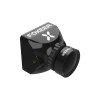
The Foxeer Predator Micro is a 19mm-class analog FPV camera that connects to power, ground and a CVBS video input. It does not use a PC driver, USB setup program or phone application.
I mounted a Predator 5 Micro in a tight canopy and the lens was slightly obstructed by a 3D printed mount edge, causing a soft blur in one corner of the image. Trimming the mount back by a couple millimeters cleared the shot completely.
The commonly listed Micro Predator 5 uses a Sony 1/3-inch CMOS sensor, 1000TVL analog output, switchable 4:3 or 16:9 video and switchable PAL or NTSC. Foxeer offers a naked and full-case version, so check the physical package before ordering a mount.
Why problems happen
Predator Micro specifications and versions
Item Specification Sensor Sony 1/3-inch CMOS Resolution 1000TVL CVBS Aspect ratio 4:3 default, 16:9 switchable Video system PAL default, NTSC switchable Input 4.5V to 20V Body 19…
Power and wiring
The official input range is 4.5V to 20V. A regulated 5V, 9V or 10V output is usually easier to keep clean than raw battery voltage. Measure the output before connecting the…
How to correct them
Camera menu settings
The Predator Micro menu includes aspect ratio, PAL or NTSC, flip, Super WDR, noise reduction and scene modes. The flight OSD can also show camera voltage, a title, time or…
Mounting and lens protection
Install the camera so the frame does not press on the lens barrel. Leave enough clearance for camera tilt and for the menu connector if you plan to adjust settings later. A front…
Predator Micro specifications and versions
| Item | Specification |
|---|---|
| Sensor | Sony 1/3-inch CMOS |
| Resolution | 1000TVL CVBS |
| Aspect ratio | 4:3 default, 16:9 switchable |
| Video system | PAL default, NTSC switchable |
| Input | 4.5V to 20V |
| Body | 19 x 19mm |
| Weight | About 5.8g naked or 6.3g full-case, excluding cable |
The M8 lens version has a published horizontal field of view around 125 degrees and diagonal field of view around 155 degrees. A separate full-cased 19mm Predator 5 uses an M12 1.7mm lens and should not be treated as the same lens assembly.
The naked camera is lighter, but the PCB and connector have less impact protection. The full-case version is easier to mount and protects the board edges, although it needs slightly more space.
Power and wiring
The official input range is 4.5V to 20V. A regulated 5V, 9V or 10V output is usually easier to keep clean than raw battery voltage. Measure the output before connecting the camera, especially after changing a flight controller or repinning a plug.
- Remove props and attach the VTX antenna.
- Confirm the camera connector pin order.
- Connect positive to a clean regulated pad.
- Connect ground to a nearby ground pad.
- Connect video to CAM for OSD or directly to VTX for testing.
- Power on through a smoke stopper and check the image.
Do not assume that every three-pin camera connector has the same order. Check positive, ground and video labels. A plug can fit mechanically while placing battery power on the video pin.
Mounting and lens protection
Install the camera so the frame does not press on the lens barrel. Leave enough clearance for camera tilt and for the menu connector if you plan to adjust settings later.
A front bumper can protect the lens, but it must not block the field of view. Check the live image for dark corners after fitting TPU guards or a narrow canopy.
First test before props are installed
- Verify the camera image with motors stopped.
- Confirm 4:3 or 16:9 matches the goggles.
- Confirm PAL or NTSC matches the FC and receiver.
- Check Betaflight OSD placement.
- Run motors slowly and watch for lines or rolling.
- Secure the camera only after the view is correct.
Run the test on a current-limited smoke stopper when possible. Keep props removed. A wiring error is easier to correct before the camera, flight controller or VTX becomes hot.
Predator Micro troubleshooting
| Symptom | Meaning | Action |
|---|---|---|
| OSD on black background | Camera side fault | Measure power and check CAM input |
| Image without OSD | FC OSD path fault | Check VOUT and OSD settings |
| Static | RF path fault | Check VTX, antenna and channel |
| Rolling image | Format or ground issue | Match format and inspect ground |
| Dark ground, bright sky | Exposure setup | Enable WDR and test scene mode |
OSD is visible but the camera image is black
The flight controller and VTX are sending a valid output. Measure voltage at the camera while connected, not only at an empty pad. Inspect the ground wire and move the camera video wire directly to the VTX for a short test.
Camera image is visible but Betaflight OSD is missing
The camera and VTX are working. Check the flight-controller video output, OSD chip configuration and the selected video format. A PAL or NTSC mismatch can place elements outside the visible area.
Image rolls or changes colour
Check ground continuity and format selection. A weak ground can create a picture that works on the bench but rolls when the motors draw current.
Video becomes noisy with throttle
Use regulated camera power, route video away from ESC phase wires and verify the battery capacitor. If the noise remains, test with the camera and VTX powered from a clean bench supply to separate electrical noise from RF interference.
Conclusion
The Foxeer Predator Micro is a compact analog racing camera with flexible aspect-ratio and format settings. Correct connector order, clean power and a shared ground are more important than changing many menu values.
For diagnosis, bypass the flight controller and connect the camera directly to the VTX. That single test quickly separates a camera or transmitter problem from the FC video path.
Frequently Asked Questions
What size is the Foxeer Predator Micro?
The common Micro Predator 5 body is 19 x 19mm. Check whether your version is naked or full-case before choosing a mount.
What voltage does the Predator Micro accept?
The official Micro Predator 5 page lists 4.5V to 20V input.
Does it support both PAL and NTSC?
Yes. The common Predator Micro version allows PAL and NTSC selection through the camera menu.
Can it switch between 4:3 and 16:9?
Yes. The standard setting is 4:3, and 16:9 can be selected.
Why is the picture noisy only when motors spin?
That usually indicates electrical noise from the ESC or power rail rather than a failed image sensor.
Sources
Ryan has flown, mounted, and mic’d up more gear than he can count, and shares the practical lessons at softwaredriverdownload.com.