The Foxeer M10Q 180 is an 18mm GPS module with an M10 receiver and an onboard compass. Connect GPS TX and RX to a free UART, connect SDA and SCL for the compass, then set the correct compass rotation for your exact module revision.
I installed an M10Q 180 GPS module and GPS rescue kept failing to arm until I gave the module a clear view of open sky for the first fix, away from carbon fiber and other electronics that were blocking part of the antenna’s view.
The important detail is that Foxeer has sold more than one M10Q 180 compass version. The older QMC5883 model and the current IST8310 V2 use different orientation guidance, so copy the setting from the product page and board markings rather than from a random build photo.
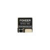
Key specifications
| Item | Details |
|---|---|
| GPS chip | u-blox M10 generation |
| Satellite systems | GPS, GLONASS, BeiDou, Galileo and supported augmentation systems |
| Channels | 72 |
| Input voltage | 5V |
| Update rate | 1Hz to 10Hz, default 10Hz |
| Default baud | 115200bps |
| Current V2 compass | IST8310 |
| Older compass version | QMC5883 |
| Size | 18 × 18 × 8mm |
| Weight | About 7.5g |
Identify the compass version
Foxeer lists a current M10Q 180 V2 with an IST8310 compass. An older product uses a QMC5883 compass. The physical size is similar, but the recommended Betaflight alignment is not the same.
Read the product label and board markings. Record the plug direction and the antenna face. Do not assume a setting named 180 belongs to the physical rotation of every M10Q 180 module.
Wiring the GPS UART
Connect module TX to a flight-controller RX pad and module RX to the matching TX pad. Connect 5V and ground to a clean regulated supply. The GPS can receive location data without the compass wires connected.
- GPS TX → FC RX on the selected UART
- GPS RX → FC TX on the same UART
- 5V → regulated 5V pad
- GND → nearby ground pad
Wiring the compass
Connect SDA to SDA and SCL to SCL on the flight controller. These are I2C lines, not ordinary UART pads. Keep the compass wiring away from motor phase wires, battery leads and high-power VTX cables.
The compass should appear only after the correct hardware and firmware support are enabled. If GPS works but the compass is missing, focus on SDA, SCL, orientation and sensor detection rather than the GPS UART.
Betaflight GPS configuration
- Enable GPS on the UART used by the module.
- Select the protocol supported by the module, normally UBLOX.
- Set a compatible baud rate or allow automatic configuration.
- Enable the magnetometer when the build requires a compass.
- Set the board or compass alignment for the exact mounting direction.
- Save, reboot and test outdoors.
The module defaults to a high update rate and fast serial speed. A flight-controller target or firmware build that cannot configure it automatically may need manual serial settings.
Compass orientation for the 180 variants
Foxeer lists the current IST8310 V2 with the plug facing forward and the antenna facing upward, using a Betaflight rotation described as clockwise 270 degrees with flip. The older QMC5883 page lists a different clockwise rotation with flip.
Treat these as starting points for the exact product revision. Confirm the heading on the bench by rotating the complete aircraft slowly and checking that the compass heading moves in the correct direction.
Mounting for faster satellite lock
Mount the ceramic antenna facing the sky. Place it away from carbon cover plates, high-current wires and the VTX. A rear mast or elevated TPU mount often locks faster than a module buried beside the ESC.
- Keep the antenna face unobstructed.
- Twist power and ground together.
- Route the UART wires away from motor leads.
- Do not place the module directly above the VTX.
- Use a small capacitor or filtered rail only when noise is confirmed.
GPS Rescue setup and testing
GPS Rescue can help recover a Betaflight quad, but it is not the same as a fully autonomous camera-drone return system. It needs a valid home point, enough satellites, correct direction information and values suited to the aircraft.
Test rescue in a large open area at a safe altitude and short distance. Keep the switch ready to cancel. Do not rely on it over people, buildings or water until repeated tests show predictable behaviour.
Common M10Q 180 problems
| Symptom | Likely cause | First check |
|---|---|---|
| No GPS icon or no satellites | Wrong UART, baud or wiring | Verify TX-to-RX crossover and the selected UART |
| Slow satellite lock | Poor sky view or electrical noise | Move the module away from VTX and battery leads |
| Compass points the wrong way | Orientation setting does not match mounting | Use the board arrow and apply the correct rotation |
| GPS Rescue climbs or turns badly | Home point, direction or rescue values not verified | Test at low risk before relying on the feature |
| Position jumps | Loose module or noisy power | Secure the module and use a clean regulated 5V supply |
When satellite count stays at zero, move outside before changing settings. Roofs, windows, carbon and a powered VTX can block or desensitise the receiver.
If the heading is wrong by a fixed angle, the alignment setting is probably wrong. If it changes unpredictably with throttle, electrical or magnetic interference is more likely.
NMEA, UBLOX and update-rate notes
Foxeer lists dual NMEA and UBLOX support. Betaflight normally uses the UBLOX protocol for configuration and navigation features. Avoid changing the protocol with third-party tools unless you can restore the original settings.
A higher update rate does not fix poor signal quality. Stable satellites, low noise and correct mounting matter more than forcing the maximum rate.
Sources and further reading
Conclusion
Use the correct UART and I2C wiring, mount the antenna with a clear sky view and verify compass orientation on the complete aircraft. Test GPS Rescue in a low-risk area before relying on it.
Frequently Asked Questions
Does the M10Q 180 include a compass?
Yes. The current V2 uses an IST8310 compass, while an older version uses QMC5883. Verify the exact module.
Which voltage should I use?
Foxeer specifies a 5V input.
Which UART pads are used?
Connect module TX to an FC RX pad and module RX to the matching TX pad.
Why does GPS work but the compass does not?
GPS uses the UART, while the compass uses SDA and SCL. Check the I2C wiring, sensor support and orientation.
Can it be used for Betaflight GPS Rescue?
Yes, but rescue must be configured and tested carefully in an open area before it is trusted.
Ryan has helped many readers work through confusing model numbers and firmware versions on niche electronics, and writes about it at softwaredriverdownload.com.